【Introduction】This article describes the role of DC/DC converters with reinforced isolation in IGBT systems, including Standard switches for power electronics, Stress testing of DC/DC converters, Comparing like with like, Comprehensive product range of IGBT applications.
IGBTs – devices that combine the characteristics of bipolar transistors and metal-oxide-semiconductor field-effect transistors or MOSFETs – are power electronics used in applications where fast switching is essential. Since they normally float at a high potential, the quality of the isolation between the driver electronics and the power supply determines the reliability of the entire circuit. This article describes the role of DC/DC converters with reinforced isolation in IGBT systems.
The political move towards renewable energy has accelerated the development of "green electronics". Priority is now given to electricity from renewable sources, mainly from wind turbines and solar power plants. Photovoltaic cells produce direct current whose amperage is determined by the intensity of the captured sunlight. Wind turbines produce alternating current, whereby the frequency depends on the wind speed. These two forms of electricity are therefore not suitable for direct feed to the grid and need to be converted.
This is done by means of highly efficient, high-power inverters. In a first step, a DC voltage with constant amplitude is generated. In a second step, the current is converted into a high-frequency current, pulse-width modulated and smoothed. IGBTs (Insulated Gate Bipolar Transistors) are used as fast-acting power switches whose drivers are supplied through small, DC/DC converters that are well isolated. The quality of the isolation determines the reliability of the overall system.
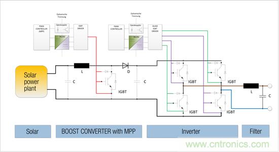
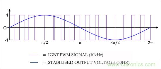
Fig. 1: Functional diagram of a solar power plant with boosters and inverters (top). Each IGBT driver is supplied through a well-isolated DC/DC converter.The device is controlled by means of a high-frequency PWM signal whose output is smoothed to a sine wave (left).
Standard switches for power electronics
Similar to MOSFETs, IGBTs are components that can be actuated with minimum current, and like bipolar transistors, they operate at an extremely low collector-emitter voltage. This makes them ideal for the switching of high voltages and current with minimum power consumption.
In simple inverters, two IGBT pairs are controlled in phase opposition by a PWM signal whose frequency is at least 10kHz. To achieve satisfactory efficiency, the switching edges must be very steep. Since the control signals are generated by microcontrollers, however, the edge angle istoo low to directly actuate the IGBTs. It is therefore necessary to install IGBT drivers that accelerate the switching process to around 1000V/µs. As the IGBTs tend to float at a high potential, the non-isolated control logics must be separated by means of optocouplers. In addition, the supply voltage of the driver, which is normally between +15V and -9V, must also be isolated. This is done through appropriately isolated DC/DC converters.
[page]
Stress testing of DC/DC converters
At first sight, the requirements regarding the isolation voltage of the DC/DC converters do not appear to be particularly stringent. Because the AC voltage does not exceed peaks of 650V, one would assume that an isolation voltage of 2kVDC for 1 second would be sufficient, as the corresponding general formula suggests. Things are, however, much more complex.
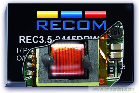
Fig. 2: The transformer and the area immediately around it determine the quality of the isolation.
The REC3.5 from RECOM shown here provides reinforced isolation up to 10kVDC/sec.
The REC3.5 from RECOM shown here provides reinforced isolation up to 10kVDC/sec.
The isolation of a DC/DC converter and thus the air and paths and the creepage paths around the transformer are generally specified for 50Hz. For efficiency reasons, IGBT switches work at frequencies that are significantly greater than 10kHz, while 300kHz are not uncommon! At such frequencies, the electromagnetic components and materials show a completely different behavior. The step edge puts additional stress on the isolation of the DC/DC converter since the extremely high dV/dt of the switching edges (around 1000V/µs) results in very large amplitudes at voltage peaks, due to coupling capacitance and other hidden capacitance occurring in the circuit between the conducting tracks and the transformer. The results of measurements with appropriate measuring technology are, however, not very reliable. This is due to the fact that the behavior of the system changes as soon as an oscilloscope probe is connected. A measured voltage peak of, say, 2kV is already attenuated by the probe, so that the actual peak might actually be much higher.
There is no ready-made formula for such peaks, and it is therefore not possible to accurately calculate the behavior of the electromagnetic materials at high frequencies. It is thus necessary to apply a generous safety buffer based on empirical values. From experience, we know that the service life of an IGBT circuit depends directly on the quality of the isolation of the DC/DC converter. Better isolation does, however, not automatically mean a higher isolation voltage, but instead it generally refers to the quality of reinforced isolation known in medical electronics. One must keep in mind that the above effects do not generally lead to instant defects or faults. Similar to a dyke that becomes weaker the longer it is under pressure from high water and then suddenly bursts, frequent near-limit loads tend to lead to a point where the isolating barrier in the DC/DC converter eventually fails. This has, of course, devastating consequences for the entire system.
Comparing like with like
In certain data sheets, the isolation voltage is specified for 1 second. In others, it is specified for 1 minute or even as a continuous value. The longer the load time is, the lower the permissible voltage will be. To enable users to determine this crucial value accurately, RECOM provides a free ISO Calculator tool. The CD-sized disk contains the relevant reference values for the isolation specifications. The ISO Calculator can be ordered free of charge by writing to info@recom-electronic.com. Alternatively, it is available as an online tool at www.recom-electronic.com.
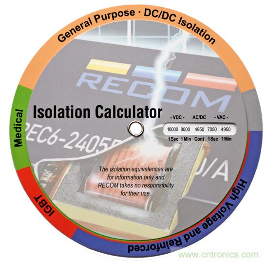
Fig. 3: RECOM''''s data disk containing relevant reference values for all isolation specifications.
Apart from the test voltage level, the quality of the isolation is of major importance. The simplest form of isolation, known as functional isolation, is achieved by means of a transformer where the primary and the secondary windings are placed directly on top of one another. The thin layer of varnish on the copper wires can withstand test voltages or around 1000VDC/1s. This varnish can, however, become brittle over time, especially if it is exposed to high ambient temperatures, humidity, vibration, or short voltage peaks. At some stage, it might fail, even if the specifications would suggest otherwise.
That is why UL (Underwriters Laboratories) has defined three distinct quality classes with clearly specified air and creepage distances. The air path is the direct distance between two points, the creepage distance is the path along the surface. To conform to the lowest UL class "Basic", a converter with an input voltage of 24VDC must have air and creepage distances of 0.5mm and 1.0mm, respectively. These values are doubled to 1.0mm and 2.0mm, respectively, for class "Supplementary". For the top class with reinforced isolation, the above converter must offer creepage clearances of 2.0mm and 4.0mm, respectively, four times those of the "Basic" class.
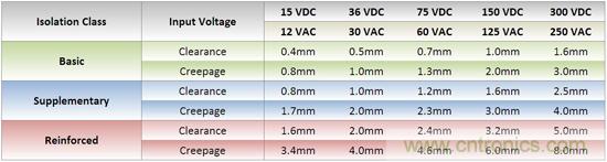
Fig. 4: The UL specifications for air and creepage clearances in medical electronics
with reinforced isolation offer improved safety in IGBT circuits.
with reinforced isolation offer improved safety in IGBT circuits.
Medical electronic devices always require reinforced isolation. There are no equivalent specifications available for power electronics. It can, however, be assumed that converters with reinforced isolation are better protected against stress occurring during the service life of the device than converters with basic or even only functional isolation. That is why more and more manufacturers use reinforced-isolation DC/DC converters for IGBT applications, despite the slightly higher costs. With its new transformer concept, RECOM has been able to make reinforced-isolation converters not only more compact but also cheaper. This means that safety is no longer a question of price.
[page]
Comprehensive product range of IGBT applications
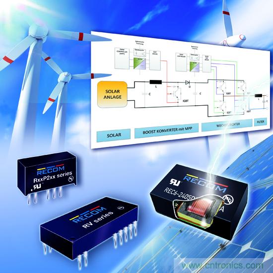
Apart from a number of converters with functional isolation, RECOM now offers high-isolation products in its 1W and 2W series RK (4000VDC/1sec), RP (5200VDC/1sec) and RV (6000VDC/1sec). These devices are already being widely used in IGBT applications. The latest series available from RECOM are the RxxP and the RxxP2 with isolation voltages of 6400 and 8000VDC/1s, respectively. They are rated for 1W or 2W and are also available as reinforced-isolation converters in compact SIP7 housings. The 2W version of the RV series is now also available with DIP24 housing for drop-in installation in existing designs. Because of an efficiency of nearly 88%, the operating temperature can be as high as +85°C without active cooling or derating.
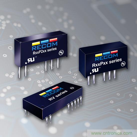
Fig. 5: Despite the compact design, the 1W and 2W series are available with reinforced isolation up to 8kV/DC/sec.
The two most powerful REC series with isolation voltages of 8000 or 10,000VDC/1s are equipped with DIP24 housings. At 3.5W or 6W, their power is about 20% higher than that of comparable models without reinforced isolation, and they offer an excellent efficiency of up to 86%. which also makes an operating temperature of +85°C for the REC3.5 and +75°C for the REC6 possible without active cooling or derating. The permissible housing temperature is +105°C.
Despite the much more complex isolation design, the above products are only slightly more expensive than devices with conventional technology. All products come with a 3-year warranty that is customary for RECOM converters. During the development phase, all products undergo extensive HALT tests in the RECOM environmental lab so that their service life is guaranteed.